

Fault Fiter® Electronic Power Fuse
For indoor distribution, 4.16 kV through 25 kV
Offering unmatched high-speed circuit-interrupting performance without producing excessive voltage surges
Fault Fiter Electronic Power Fuses are a major advancement in circuit-interruption technology. They integrate state-of-the-art electronics with an advanced-design high-continuous-current fuse. The electronics provide current sensing, time-current characteristics, and control power. No remote relaying or external power is required. Fault Fiter provides unsurpassed high-speed interruption of fault currents to 40,000 amperes RMS symmetrical. Fault Fiters are maintenance-free, maintenance-proof.
S&C’s Fault Fiter Electronic Power Fuses are manufactured in accordance with a quality system certified to ISO9001:2000.
Fault Fiter Electronic Power Fuses offer superior coordination with source-side overcurrent relays and load-side feeder fuses. They offer unmatched high-speed circuit-interrupting performance without producing excessive voltage surges, and they respond more quickly to high-current faults than conventional fuses. They’re ideal for:
- Service-entrance protection and coordination,
- Transformer protection,
- Underground subloop protection, and
- Overdutied device protection.
Fault Fiter Electronic Power Fuses are available with Uni-Rupter®, which provides 400-ampere single-pole live switching of single-phase and three-phase circuits rated 13.8 kV, and 200-ampere single-pole live switching of circuits rated 25 kV. Uni-Rupter offers the ultimate in live-switching simplicity: a firm, steady opening pull on the fuse with a hookstick is all that is required for circuit interruption. Since circuit interruption is internal to Uni-Rupter, there’s no external arc or flame.
Fault Fiter Electronic Power Fuses are offered in S&C Custom Metal-Enclosed Switchgear, S&C PME Pad-Mounted Gear, S&C PMH Pad-Mounted Gear, and wall-mounted S&C Metal-Enclosed Fuses.
(On mobile, swipe left for remaining ratings information.)
| Style | kV | Amperes, RMS | |||||
|---|---|---|---|---|---|---|---|
| Nom. | Max | BIL | Cont. | Load Dropping | Interrupting, Sym. | ||
| 60 Hz | 50 Hz | ||||||
| Disconnect with Uni-Rupter | 13.8 25 |
17.0 29 |
95 125 |
400 200 |
400 200 |
14 000 12 500 |
11 200 10 000 |
| Disconnect | 4.16 13.8 25 |
5.5 17.0 29 |
60 95 125 |
600 600 600 |
— — — |
40 000 40 000 40 000 |
40 000 40 000 40 000 |
Fault Interruption — How It Works
There are two fundamental modes of operation: the inverse-time mode, and the instantaneous mode that provides current-limiting protection for system equipment and conductors.
The inverse-time mode incorporates special electronic counters that provide an appropriate delayed response based on the fault current magnitude. The TCC can be tailored to meet the special coordination requirements of the application.
The instantaneous mode provides current limitation whenever the rate-of-rise of current exceeds the threshold value determined by the control module.

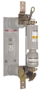
Disconnect Style (600-ampere)
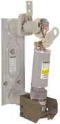
Disconnect with Uni-Rupter Style
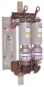
Disconnect Style (1200-ampere)
Fault Fiter® Electronic Power Fuse Time-Current Characteristic Curves
| Curve Type | Fuse Type | TCC Number | Excel | |
|---|---|---|---|---|
| Minimum Melting | Fault Fiter | TCC Number 420-7 | EXCEL | |
| Total Clearing | Fault Fiter | TCC Number 420-7-2 | EXCEL |
| Curve Type | Fuse Type | TCC Number | Excel | |
|---|---|---|---|---|
| Minimum Melting | Fault Fiter | TCC Number 400-7 | EXCEL | |
| Total Clearing | Fault Fiter | TCC Number 400-7-2 | EXCEL |
| Curve Type | Fuse Type | TCC Number | Excel | |
|---|---|---|---|---|
| Minimum Melting | Fault Fiter | TCC Number 410-7 | EXCEL | |
| Total Clearing | Fault Fiter | TCC Number 410-7-2 | EXCEL |
| Curve Type | Fuse Type | TCC Number | Excel | |
|---|---|---|---|---|
| Minimum Melting | Fault Fiter | TCC Number 422-7 | EXCEL | |
| Total Clearing | Fault Fiter | TCC Number 422-7 | EXCEL |
| Curve Type | Fuse Type | TCC Number | Excel | |
|---|---|---|---|---|
| Minimum Melting | Fault Fiter | TCC Number 421-7 | EXCEL | |
| Total Clearing | Fault Fiter | TCC Number 421-7 | EXCEL |
Parallel Fault Fiter® Electronic Power Fuses
| Curve Type | Fuse Type | TCC Number | Excel | |
|---|---|---|---|---|
| Minimum Melting | Fault Fiter | TCC Number 410-7-P | EXCEL | |
| Total Clearing | Fault Fiter | TCC Number 410-7-2-P | EXCEL |
![]() Not Available. Please contact your S&C Sales Office to obtain a copy.
Not Available. Please contact your S&C Sales Office to obtain a copy.


